
- RF power handling rating and derating considerations
- Frequency capability
- Connector types (SMA, N, BNC, TNC, waveguide, etc.)
- RF impedance
- Insertion loss
- Isolation (from common input to Off output)
- Switching time(s) and PTT sequencing considerations
- Operating voltage, current and heat dissipation
- Actuator type (solenoid, latching, etc.)
- Switching voltage spikes
- Packaging and operating environment
- "T/R" versus "R/T" connection for fail-safe and overload considerations
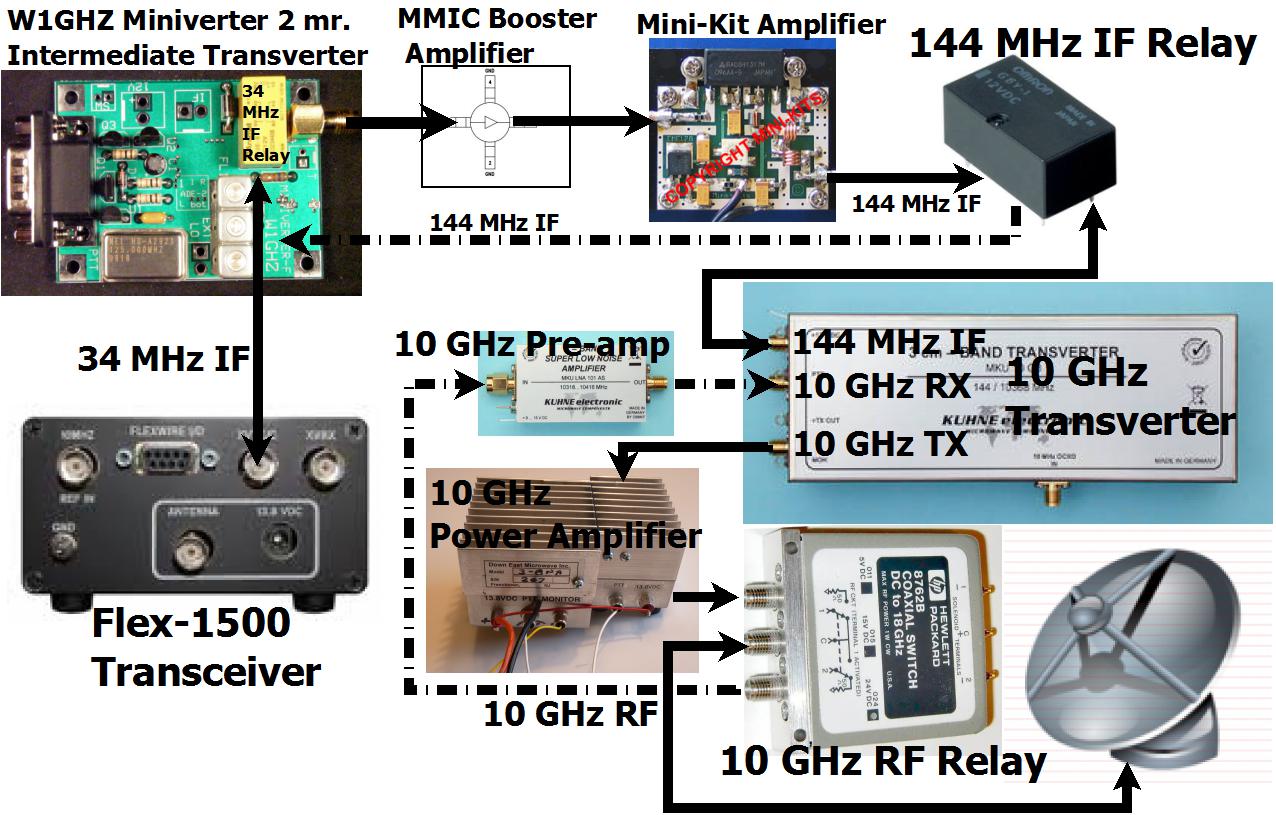
- Switching of a 28 MHz transceiver IF output port between the TX and RX inputs on the intermediate transceiver (usually 144 or 432 MHz).
- Switching of a 144 or 432 MHz transceiver or intermediate transverter 144 or 432 MHz IF output ports to a match a common IF input port on the 10 GHz transverter.
- Switching of the 10 GHz transverter TX and RX output ports to an antenna.
- Switching of 10 GHz power amplifiers.
- Protection of receiving pre-amplifiers.

One of the most popular RF Coaxial Switching Relays found at swapfests and on E-bay is the 28 VDC, Solenoid, SMA type:


These are priced from $25 to $50; depending on specifications, brand, condition and seller. Most of them are labeled with NC, COM and NO ports. Unless you already have 28 VDC power available, this can increase the complexity of your station.
Latching relays are usually lower in price due to the lessor demand. Most often the ports are labeled 1 and 2. Often they offer good performance but with the added complexity of the latching pulse control circuitry. Some are available with a 12 VDC coil but most are 28 VDC.


The latching circuitry (picture below) can be obtained as a kit:

- Latching Relay Driver from W6PQL
- Roll your own with this Maxim chip
There are several ways of dealing with the 28 VDC power requirement:
- Rewind the coil for a lower voltage, usually 12 VDC.
- Use a 28 VDC relay driver kit:
- RVD-1 from Down East Microwave (look under accessories)

3. Some of the newer transverters have a built-in 28 relay driver:
- 10368-144 transverter from Down East Microwave

4. Use a 12 to 28 voltage booster to provide the up to 28 VDC relay coil voltage. Generated RFI is usually an issue unless you're careful to shield the voltage booster and bypass both the 12 and 28 VDC cables.
- 12 to 28v voltage booster kit from W6PQL

"T/R"versus "R/T" Relay Configuration?
Conventionally, the "NC" (Normally Closed) set of relay contacts are used for the receive RF path and the "NO" (Normally Open) set of relay contacts are used for the transmit RF path. However, your transverter "front end" pre-amplifier (or external receive pre-amplifier) can be exposed to high levels of RF from other nearby 10 GHz stations or from 5.7 GHz when using a dual band feed.
That's why I prefer the more protective "R/T" relay configuration where the "NO" relay contacts are used for the receive path and the "NC" relay contacts are used for the transmit path. If the relay (or 28 VDC power) fails, it usually defaults to the "NC" position and the transmit RF is routed to the antenna. Click on diagram below for a larger view.

One unanticipated consequence was that the powered On duty cycle during receive is usually much longer and therefore tends to heat up the relay (unless it's a latched relay). This could contribute to a relay failure if the relay case is confined with no airflow or direct sunlight.
Relay Insertion Loss, Isolation and Switching "Bounce"
An electro-mechanical relay isn't an ideal device. It dissipates some power (Insertion Loss) in the conducting path while leaking some power (Isolation) into the non conducting path. It also takes some time for the internal contacts to complete the switching (contact bounce) after voltage is turned On or Off. Lastly, there's a nasty voltage spike generated when the voltage across the relay coil is switched. All of these real-world particularities need to be taken into consideration at the operating frequency of interest. Most of the latching relays that I've tested have had relatively low loss and high isolation @ 10 GHz. Many of the non-latching relays have also had good measurements except those that failed prematurely or were DOA (beware of E-bay or swap-fest "good deals" from unknown sellers). Click on graphs below for a larger view.


Usually a pulse width of 30-50 ms is sufficient to guarantee setting of the latch and exceeding the contact bounce period. Also, the duration of the contact bounce period increases as the voltage decreases!
Contact Bounce while turning "Off" measured at 14 VDC:

Contact Bounce while turning "On" measured at 14 VDC:

Testing Microwave Relays
First, look for an on-line data sheet. This will help you know what to expect and to not exceed the power rating.
Lacking a network analyzer, I'm forced to use bruit force to help sort out my pile of relays. It's advisable to test them at the actual operating frequency so that you know what you're getting. Stress testing at full transmit power would be my choice although it can be difficult to get repetitive results that are consistent. I use a "reference" relay of known characteristics and a female-to-female SMA adapter for A vs B vs C testing. My test setup uses a power meter (HP 432C), power head (HP 478A) and "good" power attenuator (Weinschel 30dB 10W <12GHz). Any component that introduces measurable SWR downstream from the relay under test can void the test results (be very careful with unknown adapters, cables and connectors). Repeat the setup multiple times as you rotate through A vs B vs C devices. Throw out the high and low results and average the remaining samples before you make comparative conclusions.
Relays that are marginal at 10 GHz may be quite acceptable when tested at lower frequencies. Relays used downstream of receive pre-amplifiers may have higher loss than the antenna relay (upstream of both the receive pre-amplifier) as their loss degrades the overall system noise figure.
Relays used on the IF end of the transverter can also have higher loss as there usually is plenty of IF power at the lower IF frequency to make up for minor relay losses.
The Care and Feeding of Relays
Click here to return to Contents and Navigation.
No comments:
Post a Comment